
Projects MB-470
Radio design In design
MB-470
HF through UHF
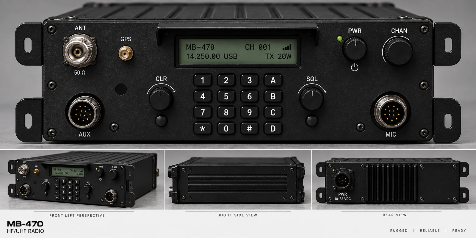
A radio of my own, drawn from scratch and deliberately superheterodyne rather than software defined. Ten years of sketching, calculating and revising, built on what I learned keeping a URC-94 and a GRC-171 running, and on what carrying a PRC-150 taught me about how a radio should sit in the hand.
- Architecture
- Superheterodyne, by choice
- Coverage
- HF through UHF
- Started
- 2015
- Stage
- Design, moving to hardware
- Panel, as drawn
- N-type 50 Ω, GPS, AUX, MIC, 16-key pad
- Supply, as drawn
- 10 to 32 V DC
The URC-94
I have years of experience operating, maintaining, and repairing the URC-94 radio set, and when it comes to HF radios, the URC-94 is still the love of my life. It is an absolute tank and a drama queen at the same time. When she breaks, she tends to break hard. But when she is properly maintained and cared for, she will run seemingly forever.
Her antenna coupler can be every bit as temperamental, particularly when dealing with spark-gap issues and capacitor failures. In my experience, many of those problems were not inherent design flaws, but the result of poor environmental sealing, pressurization, or maintenance practices. When the system is properly maintained, it is remarkably capable.
Five days at twenty watts
The URC-94's cousin, the GRC-171(V)2, is equally impressive. I once operated one at essentially a 100 percent duty cycle for five straight days, transmitting continuously at 20 watts. It never stopped. No faults, no blown components, no significant failures. Experiences like that gave me a tremendous appreciation for how these radios were engineered and how much margin was designed into them.
Over the years, I took the intimate knowledge I gained from operating, troubleshooting, and repairing these two radios and began applying it to a radio design of my own, intended to cover HF through UHF. I deliberately chose a traditional superheterodyne architecture rather than an SDR approach.
What the manpacks taught me
I have also spent plenty of time carrying and operating the PRC-150 and PRC-117 series radios, and I developed a different kind of appreciation for them. They are durable bricks that can take a beating, but their mobility, packaging, ergonomics, and overall physical design are what really influenced me. Much of the inspiration for the form and field usability of my own radio comes from those systems.
Since around 2015, I have been brainstorming, sketching, calculating, revising, and slowly working my way toward a complete radio design.
Why superheterodyne
There is something about the architecture of a well-designed superheterodyne radio that I genuinely love. I appreciate being able to understand the signal path circuit by circuit and stage by stage. I appreciate design details such as deriving a true sidetone sample from the transmit audio at the T/R switching point and feeding that actual sample back to the operator's headset. Those details may seem small, but they demonstrate how thoughtfully some of these systems were engineered around both the signal and the person operating the radio.
That is not meant as criticism of modern radio design. Modern SDR architecture is remarkable in its own right, and software-defined systems achieve an entirely different kind of simplicity, flexibility, and capability. My preference for superheterodyne architecture is simply rooted in what I enjoy about radio engineering: understanding and designing the physical signal chain and knowing exactly what is happening to the signal as it moves through each stage.
Where it stands
After more than a decade of thinking about this radio, drawing it, doing the math, changing things, and applying lessons learned from the equipment I have worked on, pencil, paper, calculations and schematics are no longer enough.
If I want to find out whether the radio I have been designing since 2015 actually works the way I believe it will, I have to start putting real money into hardware and bring it to life.
Still to come
What goes up next
- The block diagram: the full signal chain, stage by stage, receive and transmit.
- Front panel and chassis drawings, including the hole schedule and the machined faceplate.
- The band plan and the filter and mixer scheme behind HF through UHF coverage.
- The sidetone path, taken off the transmit audio at the T/R switch rather than generated separately.
- A parts and cost breakdown as hardware starts getting bought.
This is the first entry on the MB-470, not the whole of it. The design has been in progress since 2015 and the pages here will follow it as it moves off paper.